
3D is a neat indoor and light wind outdoor kite made by Prism. I enjoy flying it from time to time, however I find that it is too small to do the tricks the way I like them. It only takes a few centimeters of movement by your fingers to make the kite pull a tight spin. It will dead lanch if the lines are short enough, or if the surface is smouth enough (its hard to dead launch outdoors, you almost have to jump, and pull up at the same time).
Frame:
The kite origionally is built of half ounce Icorex. and uses 1 onze nylon for the trailing edge and leading edge. The kite is manly framed in Avia .098" MicroCarbon and is almost unbreakable. The upper spreader is made of Avia .068" MicroCarbo and the Standoffs are Avia .053" MicroCarbo.
| Part | Rod | Length | Comments |
| Spine | 0.098 | 49.8 cm | two vinyl end caps |
| Top Spreader | 0.068 | 35.8 cm | two vinyl end caps to make top spreader fit into LE connectors |
| Bottom Spreader | 0.098 | 97.9 cm | Join at spine with 0.4 cm wite cut rubber hose |
| Leading Edge x2 | 0.098 | 102.0 cm | Vinyl end cap at nose |
| Inner Standoff x2 | 0.053 | 16.3 cm | 0.5 cm that sticks out past kite sail |
| Outer Standoff x2 | 0.053 | 12.5 cm | 0.5 cm that sticks out past kite sail |
Bridle:
Knots at Leading edge and cross spreader should be done as so. When pulled tighed, the knot at the end of the line holds everything tight.
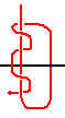
The green line is connected to the red line using a single larks head knot, however the blue loop is connected as usual using a double larks head knot.
Standoff:
Standoffs are made as follows. A hole in the kites trailing edge and a larg vinyl end cap is used on the bottom spreader.

Sail:
The template for the sail has been inputed into an .MC file. The file can be read with a shareware applicatoin called MegaCad. The template is created using many layers. Each layer has different parts of the kite templates.
| 3d kite layer | Contains the outline of half the kite including the leading edge. It also has the position for the variable inner stand off and the static outer stand off. The location of the center T is also plotted along with the Leading edge connector locations |
| circles layer | This layer was added as a sample location of panels. You can put your panels almost anywhere you want. |
| grid layer | This layer is a gride at every 2.5 cm. It helps when you try and print the kite over many sheets of paper to keep everything square. |
| hem and le layer | This layer was added if you want to make the kite without using separate material for the LE. You just fold the LE and trailing edge over and sew. |
You can turn on and off each layer to depending on what you want printed or displayed on the screen.
The template does not include a pocket for the leading edge rod at the trailing edge, it can be about 4cm long and 1.5 cm wide. This is not a critical part of the kite. When printing, make sure that you print at a ratio of 1.0 to get the actuall kite size. If you print at 0.615 you get the approximate size for a Vapor kite.
Download 3DKITE.MC for the template. this can be viewed with MegaCad 1.0 available free on the net.
Same template in Windows MetaFile format 3DKITE.WMF