The Mirage is a kite with a "PRISM kite" look and feel. As we all know these kites are known for their high quality and flying characteristics. The kite presented here is inspired by PRISM kites (it's NOT copied!). 3 prototypes, lots of errors and calculations were done to get to this result. It's up to you to judge what the final result is... For us it would be rewarding to see more Mirage's in the air. Build one for your own usage only, not for commercial purposes...
Ok, now for the good part! The Mirage, built in polyester (Ventex or Icarex) and framed in wrapped carbon spars is a real miracle... It's precise, does not oversteer, doesn't pull much -not even in strong wind-, the wind window is enormous, and for those who know the secrets of dynamic bridling, it's capable of doing all the tricks and to smoothly glue them together. (ok, the flic-flac is a bit mre difficult, but that is inherent to the kites specific form).
First thing to do is to copy the plan (full-sized) onto some cardboard that you can use as a template to draw the panels on the cloth. Put all given marker points onto the board and use a solid carbon spar (2-4mm) bent along these marker points to trace the final curves. After that cut out the cardboard panel templates. When tracing the carboard panels onto the cloth, you can best put some marker points on the cloth that aid you in aligning the panels lateron. Panels (A) and (F) are made of reinforced mylar. All other panels are made of polyester.
For the correct alignment of the cloth (not shown in the plan ), the panels (C) and (D) are perpendicular to the leading edge; panel (E) is perpendicular to the trailing edge; and finally panel (B) is a compromise to being perpendicular to the spine and the leading edge.
To assemble the kite you first have to cut out the panels. Then assemble panels (B) and (C). After that assemble panels (E) and (D), and join the created (BC) and (DE) panels. The dotted line on the plan is shown with a little curve. This is not correct. In reality this seam should be straight. Now you can cut the mylar panel (F) (grain parallel to the leading edge). Panel (A) is made out of one piece (i.e. not cut along the spine), grain parallel to the spine. Assemble the two half-wings to the (A) panel.
Now for the trailing edge. Fold a 2.5 cm wide nylon strip in the middle
and use this as the trailing edge pocket. Reinforcements of the
trailing edge are made of 2.5 cm dacron strip and are placed at the
whisker positions. This reinforcement starts at 38 cm from the tail-end
and is 37 cm long. If you want to do it real nice, you can put the
reinforcement inside ofthe trailing edge tunnel
You can now make the leading edge tunnel in a similar way from of a 5
cm wide dacron band. Nothing especially difficult here, except for the
tip end: with such a curvature in the leading edge, you will not be
able to use the traditional bungee cord at the tip; to stretch the sail
correctly, youll use a short length of sleeved spectra tied at the tip
of the sail in a nylon strap. Here's how its done: start to sew the
tunnel at the nose; then, at 10 cm before the tip end, insert a 5 mm
wide nylon strap inside the casing, and sew the tunnel over this nylon
strap loop (see next picture). The lenght of sleeved spectra will then
be attached inside the loop and tied at the tip of the carbon rod to a
simple arrow knock. For the central connector, just add dacron patch on
the belly and on the back of the sail for reinforcement, as well as for
the nose, which will receive an additional reinforcement of seat-belt
webbing (somewhat uggly, but very effective). For the tail, a velcro
strap, sewed inside a piece of dacron will hold the spine tensioned and
centered.

|
The 2 lower half-spreaders are both exactly 78 cm long and the upper spreader is 57.7 cm. There are 2 whiskers for each sail. One is at 44 cm distance from the spine and is 23.5 cm long. The other one is at 69 cm distance from the spine and is 20 cm long. They are made of 1.5 mm solid carbon.
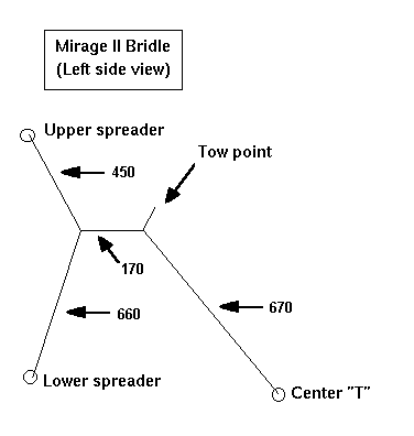
The bridle is best made dynamic. Ideally it's made of sleeved spectra but it can also be made of 30kg polyester line. The small digram below shows the basic dimensions to use, but if you use prussik knots you can adjust all that you wish.
The dynamic bridle (measurements in mm, measured between the knots)

|

|
Translation by Peter Peters