Copyright Ed Alden 2000 All Rights Reserved
Fighter kites are maneuverable because they change their shape in response to the difference in air pressure between the front and back of their sail. Under low pressure, the sail is flatter and the kite turns easily. As the pressure increases, the sail is pressed back into a dihedral (keeled) shape, which tends to travel in a straight path through the air. The flyer controls the kite by controlling when these pressure shifts occur, and therefore the direction in which the kite flies. Fighter kites are unique in that this continual "shape-shifting" is not a by-product of the design, but is the defining characteristic of their flight.
The structure of the most common fighter
kite design, the Indian diamond, and its
derivatives like the Japanese Hata, is conceptually
very simple, consisting of only four components:
the sail, the bow, the spine, and the bridle.
The spine and bow form the frame of the kite.
They support and shape the sail. The bridle
controls the alignment of the kite in the
pitch and roll axes. (Aircraft literature
speaks of three axes of rotation, pitch,
roll, and yaw. These terms are also useful
when discussing kites. Pitch is the “nose
up-nose down” axis. Roll is the “bank left-bank
right” or “barrel roll” axis. Yaw is the
“nose left-nose right” axis.)
In conventional fighter designs only the
bow and sail change their shape in response
to changing air pressure, the spine and bridle
do not. The distinguishing feature of the
Vari-Fighter is that all four components change their shape, and
the stiffness of the bow changes, as the
air pressure changes. This variability allows
the performance of the kite to be more easily
optimized across all flight regimes, without
requiring the compromises necessary in traditional
designs.
Having noted the conceptual simplicity of
fighter structure, let me pay homage to the
truth quickly encountered by all those who
build a fighter kite: a great flying kite
may seem a simple object, but it is a machine
of subtle interactions which are not fully
understood by anyone. A good fighter’s "dance-with-the-wind"
is easily appreciated by the flyer, but is
not so easily attributed to specific design
features. However, many lessons have been
learned through experience and experiment,
and there are several principles and relationships
which seem to hold true (most of the time).
The following discussion is structured around
each of the four components, the principles
and their interactions, and how variability
applies to each.
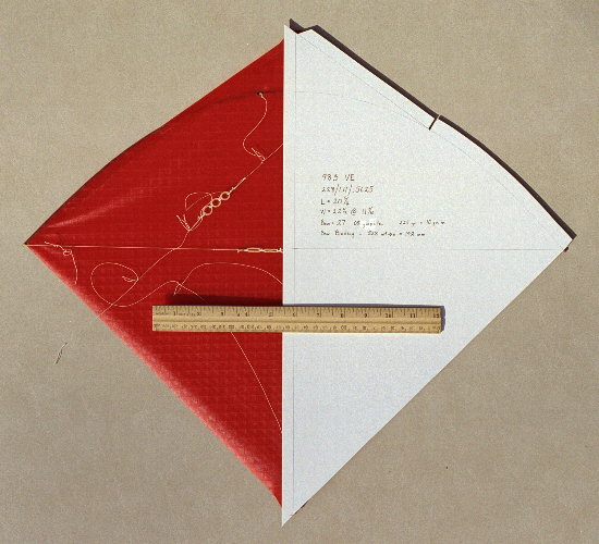
The sail is the most obvious of the kite's components. There are many different fighter kite designs around the world, usually distinguished by the plan of their sail. While the principles of variability are applicable to most fighter designs, this article will discuss what is perhaps the most common design: a diamond shaped sail where the corners form the nose, tail, and wingtips, see Fig. 1. This sail plan can be defined in a few simple formulas. I will use the same nomenclature as used in an article published in KiteLines magazine in 1993 where:
l = the length of the kite, measured from tail to nose, along the centerline.
w = the width of the kite, measured from wingtip to wingtip, perpendicular to the centerline.
t = the length of the kite from its widest point (tip point), measured to the tail along the centerline.
b = the length of the kite from where the bow crosses the spine, measured to the tail along the centerline.
S = square area of the sail = lw/2
A = aspect ratio = w/l
T = tip ratio = t/l
B = Bow cross ratio = b/l
The following relationship derives from the above formulas:
l = (2S/A)1/2
Experience has shown that the material of the sail affects how the kite flies. Two kites, identical except for their sail material, will usually fly differently. So, here is the first principle: there is no "magic" shape that is the best fighter. But there are shapes which are more "competitive", flying higher, turning better, etc. Second principle: use smaller kites in stronger winds, larger kites in lighter winds. As a guideline, practical values for the above relationships are:
| S = | 100 - 350 square inches |
| A= | .9 - 1.2 |
| T= | .5 - .7 |
| B= | .6 - .85 |
Sail materials vary in their stretch, permeability,
and smoothness. In flight, stretchy, permeable
sails feel “gentler” while stretchless, impermeable
sails feel “harder”. Tyvek, light orcon,
and ripstop nylon are gentler materials.
Linear polyethylene, ripstop polyester (Icarex),
and middleweight orcon are intermediate.
Polyester film (Mylar) is impermeable, does
not stretch, and feels “hard” to the wind.
The bow is what most clearly differentiates fighters from other kite species. It is flexed when attached to the sail. The bow’s tension is what flattens the sail, and controls how much the sail becomes concave under pressure. Several materials are commonly used as bows, but it seems that the evolution is toward the highest stiffness-to-weight ratio. Bamboo is nature’s composite material and its stiffness-to-weight ratio is difficult to equal with synthetic materials, although some builders believe pultruded graphite (carbon fiber) rod does equal or surpass it. However, getting consistent results with bamboo requires much more effort on the builder’s part and the bow is affected by humidity, etc. The most commonly encountered synthetic bow material in the USA is pultruded carbon fiber rod. It offers high performance and great consistency and stability under changing conditions.
The bow and sail interact as follows. When the sail is flatter, the kite yaws, so a bow that is strong enough to keep the sail flatter will give a “spinny” flight. A weaker bow will give a flight where the kite goes straight more easily. Strong and weak are relative to the wind speed. Third principle: No single kite can fly well in all wind speeds. Light winds require a lower relative bow stiffness; high winds require higher relative stiffness. There is some maximum energy available at any given wind speed and sail area. A fast kite extracts more of this energy for its “engine”, while wasting less in aerodynamic drag. A flatter sail is pushed harder by the wind and goes faster, so a stronger bow makes a kite go faster. But the stiffer the bow, the less dihedral, making the kite spin faster, which is harder to control while hovering and turning. Fourth principle: a good fighter embodies a well chosen compromise between speed when flying straight and ease of control when hovering and maneuvering.
The bow’s stiffness can be expressed in two
ways, absolute and relative. A bow’s absolute
stiffness is simply the pressure needed to
remove all tension from the sail. I usually
use grams. If one measures many kites, the
tension will typically fall between 40 and
300 grams.
I have used two methods for measuring the
absolute bow tension. The first was to stand
the kite on one wingtip on the platform of
a small gram scale (a kitchen scale with
springs, not a balance beam type), then zero
out the weight of the kite, then push down
on the upper wingtip slowly until I saw the
sail just begin to relax and buckle, then
read the scale. This method is very easy,
fast and works on any kite. However, I discovered
that my little scale was inaccurate, it was
off by about 15%, which is unusable, especially
for light bows.
So, my current and more accurate method is
to: attach a small lightweight plastic sack
on a piece of string to one wingtip, then
stand the kite on its other wingtip, then
put brass gram weights of various sizes into
the sack, making sure that the string holding
the sack is perfectly aligned on (pointed
at) the lower wingtip, the absolute tension
is the weight needed to just make the sail
start to buckle.
Bows without sails are also easy to measure,
and I believe more accurate. I have found
that a 1 or 2 percent change in the tension
can change the flexure by a surprisingly
large amount when the flex is in the range
useful for fighters.
If one divides the absolute tension by the
wingspan, relative stiffness is the result.
I express it as grams per inch. In conventional
designs, the relative stiffness is the most
important factor in determining the wind
range in which the kite flies best. I use
5 grams per inch for light wind kites (0-3
mph), 6.3 gr./in. for medium wind (3-6 mph),
8 gr./in. for high winds (6-12 mph), and
10 gr./in. for very high winds (12+ mph).
If one measures the absolute tension as a bow is flexed, the tension increases rapidly as flexure begins, but then rises slowly once the flexure passes a certain degree of curvature. Every fighter I've found practical has the bow flexed into this region where the tension changes slowly as flexure increases. This also holds true for bows that taper toward their ends. The shape of a flexed, tapered bow is different from a flexed, untapered bow, but the tension versus flexure relationship is the same. This region of slow tension increase is large enough to give the designer wide latitude in choosing the shape of the flexed bow. One chooses a particular degree of flexure based on how the kite flies and esthetics; there is no single best amount.
The Vari-Fighter 2000 design is significantly different from other Indian-derived fighter kites in that the stiffness of its bow is not constant! An elastic tether connecting the wingtips is adjusted so that in light wind pressures the bow flexes easily, readily producing the small dihedral needed for hovering. As the wind pressure increases and the bow's flexure deepens, the elastic tether's tension decreases, requiring stronger and stronger wind pressure for each equal increment of bow flexure and dihedral. The overall effect is a kite which flies like a lightly bowed kite at low wind pressures, but which then changes to a heavily bowed kite as the wind pressure increases. The amount of stiffness change is readily controlled by choosing the bow diameter and the elastic's strength and stretch. When correctly constructed and adjusted, the "feel" of a Vari-Fighter 2000 is instantly recognizable as being different from kites with constant stiffness bows. The degree of the compromise mentioned in the fourth principle above, stiffer bow versus lighter bow, is much reduced in a Vari-Fighter 2000, which can have a much wider wind range while offering good control and performance.
It has also been found by experience that binding the sail to the bow for some distance inward from the wingtips makes the sail “grab the wind” better. A sail that attaches to the bow only at the wingtips will pull less, and accelerate less, than one that is bound to the bow. This effect is proportional to the fraction of the bow to which the sail is bound. Binding the sail to the bow gives the best combination of speed and control. Assuming a reasonable sail shape, the relationship between sail area, bow stiffness and sail-to-bow binding is responsible for the overall “feel” of the kite, its pull, its speed, its controllability, and its best wind range.
The spine of an Indian-derived fighter lies along the centerline of the kite from nose to tail. When the air pressure is low, the bow’s tension will flatten the kite along the axis between the wingtips, and any shape the sail needs must, therefore, come from the spine. When the pressure increases, the bow flexes and the sail takes a concave dihedral shape centered on the spine. The shape of the sail under pressure is determined by 1) the sail’s plan, 2) the shape and stiffness of the bow, and 3) the shape of the spine. The spine’s stiffness and how the bridle supports the spine control the spine’s shape under pressure.
The shape of the sail along the centerline
is important to the performance of the kite.
If we define the wingtip-to-wingtip axis
as X, and the nose-to-tail axis as Y, then
the front-back axis becomes the Z-axis. Since
it runs along the Y-axis, the spine has a
shape in only two dimensions, X and Z. A
spine perfectly straight in X is usually
the builder’s goal, since the spine is like
the keel of a boat, a straight keel makes
the path traveled straight. However, the
shape of the spine in the Z (front-back)
axis is another matter. The Z-shape of the
spine affects the Z- shape of the sail, which
is really the important thing. Fifth principle: a single sail Z-shape is not optimal under
all wind pressures.
At high wind pressures (and the resulting high speeds)
a flat Z-shape is desirable for two reasons:
1) to minimize the frontal area of the kite, and
2) to minimize the fluttering of the sail’s trailing edge.
Both frontal area and flutter increase aerodynamic
drag, which slows the kite.
In contrast, at low wind pressures (and low speeds, therefore),
the Z-shape of the sail needs to be convex
toward the flyer, so that the aerodynamic
forces on the kite push it away from the
flyer, which keeps the flying line taut and
gives the flyer better control. The sail’s
Z- shape profoundly affects how easy the
kite is to fly when hovering and out near
the edge of the wind window (and beyond).
The Vari-Fighter design uses a spine that
changes shape as the wind pressure changes.
At low pressure, the
spine is curved, convex toward the flyer.
As the pressure increases, the spine is flattened
out so that the sail is flat
along the centerline at high speeds, minimizing
drag. The details of construction used to
achieve this variable
geometry in the spine will be discussed later.
Now we move on to the fourth, and last, major
component of the kite:
The bridle of a fighter kite is as important as any other component. Much previous literature has failed to give appropriate attention to the fighter bridle and its contribution to the fighter’s performance. It is the component by which the kite is “tuned” to achieve optimal control during a flying session. Shifting the relative lengths of the legs of the bridle controls the alignment of the kite in the pitch and roll axes. Fighter kites change their direction of flight by yawing, but are not significantly maneuverable by the flyer in the pitch and roll axes. Indeed, most fighters are intended not to roll at all, since rolling will prevent the kite from flying in a straight line. Fighter bridles attach to the frame of the kite, the spine and bow, and to the flying line.
To be a bit more specific about bridle construction, it is useful to distinguish between two terms, “legs” and “points”. I will define these terms as follows: a bridle point is an attachment of the bridle to the kite frame. A bridle leg is a length of bridle line that is straight when the bridle is under tension; any change in direction starts a new leg. Using these definitions, a two-point bridle is also a two-leg bridle. However, a three-point bridle may have either three or four legs, depending on its construction. A four-point bridle may have four, five, or six legs. Since it is easiest to construct adjustable connections at which only three lines converge, a three-point bridle will usually have four legs, and a four-point bridle will have six. However, it is the number of points that determines the degree of control over the kite, not the number of legs.
Most fighter literature describes a two-point bridle, which allows adjustment of the kite’s attitude in the
pitch axis only. A few publications describe the three-point bridle, which allows adjustment in both pitch and roll. I
have seen only one reference to a four-point bridle, used to keep a thin, flexible spine straight. As this is written,
most high performance fighters that place high in Western-style, “line-touching” competitions use a three-point,
four-legged bridle, which is used to tune the kite as follows:
The roll axis is adjusted so that any minor
asymmetries in the kite are “tuned-out” and
the kite will fly in a straight line when
dihedral is present. This roll adjustment
is not usually changed once straight flight
is achieved.
However, the pitch axis adjustment is typically
changed during every flying session. Moving
the nose toward the flyer (decreasing the
angle of attack, in airplane terms) makes
the kite more prone to yaw, while moving
the nose away from the flyer reduces the
kite’s readiness to yaw. A good fighter is
so responsive to changing wind speed that
the flyer will want to adjust its yawishness
for the conditions of the moment. With conventional
bridles, this tuning always involves compromise
because the kite is flying in very different
winds and at different attitudes to the wind
as it moves across the wind window. At the
edges, one would like more yawishness, at
the center, less, but conventional bridles
are “fixed-tuned”, they do not change across
the wind.
In contrast, the Vari-Fighter uses a four-point,
six-legged bridle in which one leg is elastic,
see Fig. 2. The bridle performs two functions simultaneously:
1) it changes the tuning of the kite as the
wind pressure changes, and
2) it supports the spine’s center so that the spine’s shape change does not go too far.
The elastic leg is in the upper bridle, above
the flying line connection, so that higher
wind pressure pushes the nose away from the
flyer. When the wind pressure decreases,
the elastic pulls the nose toward the flyer,
increasing yawishness. This elasticity allows
the kite to re-tune itself for the wind pressure
of the instant. On a properly functioning
Vari-Fighter, when one is flying dead downwind,
going fast, pulling hard, the kite is tuned
to go straight, not turn, and the spine is
straight, minimizing drag. When the pressure
is low, the flyer wants to turn, or the kite
is out at the edge of the wind, where kites
do not turn as well. Then the elastic pulls
the nose in, the kite is more yawish, and
the spine is curved, so the kite flies away
from the flyer and control is more easily
maintained.
One feature of the elastic bridle, which
it took me some time to recognize, is that
the end points of the range over which the
bridle changes can be more extreme than one
would ever use with an inelastic bridle.
At the edges of the wind, my kite is much
more yawish than I could ever tolerate if
I had to fly that same tuning straight downwind.
In the center of the wind, pulling hard,
the kite is tuned much less yawishly than
I could use if I had to fly that tuning out
at the edge of the wind.
The overall perception of the flyer is that
the Vari-Fighter design is easy to fly, maneuverable
at the edges, easy to hover, but fast, stable,
and straight in long pulls. Also, one does
not spend as much time tuning, since the
kite has so much adaptability built-in.
The Vari-Fighter 2000 design is an extension
of the principle of wind pressure controlled
variability into all a fighter’s components.
All Indian derived fighters vary the geometry
of their bow and sail; the Vari-Fighter 2000
varies the spine and bridle geometry as well,
and also varies the bow's stiffness. The
result is a kite that is easier to fly while
offering competitive performance. My personal
goal has been to build the highest performance
fighter possible for competing in Western-style,
line-touching competitions. However, the
Vari-Fighter design principles are completely
applicable to kites for other purposes: indoor
flight, colored fabric graphic show kites,
precision skill competitions, etc.
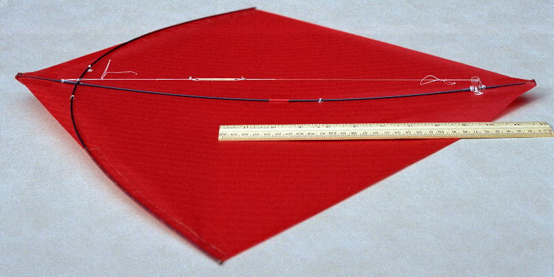
What follows is an example of a high performance design that uses Vari-Fighter principles. It is the best competition fighter design I know how to build as of March 2000. Its features have been validated in several kites of different sizes and wind ranges. This example is a medium sized, light-to-medium wind kite. Hopefully the pictures and diagrams will convey what words cannot. Photo 1 shows the sail plan, with the half pattern used for cutting out the sail laid on top.
| Size: | S = 228 sq. in |
| Aspect Ratio: | A = 1.11 |
| Tip Ratio: | T = .5625 |
| Length: | l = 20 5/16 in. |
| Width: | w = 22 1/2 in. |
| Tip position: | t = 11 7/16 in. |
Bow: length = 27 in., material = .08 in.
diameter pultruded carbon (graphite) rod,
extends 1/8 in. beyond the sail’s wingtips.
All references to the wingtips, unless specifically
noted, are to the sail’s wingtips, not to
the end of the 1/8 in. extensions, which
are there to make construction easier and
to act as a guard for the sail wingtip.
These dimensions have been chosen to construct
the largest possible kite while using just
one 48 inch long graphite rod.
flexed length = w = .84 of straight length,
excluding the 1/8 in. extensions above
tension = 225gr. yielding 10 gr./in. relative
stiffness, which would ordinarily make this
a heavy wind kite, except that the Variable Bow Stiffness feature lets this kite fly perfectly well
in very light winds also.
Sail: Ripstop Icarex fabric, ½ oz. per
sq. yd. weight.
Bound to the bow for .528 times the distance
from the wingtip to the nose, 192 mm. The
binding ends at a point on the bow which
is 192 mm from the sail wingtip, measured
in a straight line, not along the curve of
the bow.
The sail material is hot cut on glass. Hot
cutting makes the sail much less likely to
unravel, or tear, in the case of Mylar film.
My Mylar sails last for years, as long as
I keep them away from sharp things, and crash
landings.
The shape of the leading edge is, from the
wingtip: 1) the natural shape assumed by
the bow when flexed,
to the point on the bow where the sail binding
stops, then 2) a straight line to the nose.
The trailing edge is
straight.
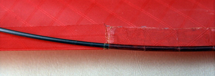
Spine: Graphite Rod, the same as is used
for the bow. The spine is flexed into a natural
curved shape by an elastic tensioner on its
back side, see Photo 2. When the tensioner is removed, the spine
is straight.
Bridle and tensioners: 12 lb. Braided Dacron
(Cortland Micron fly line backing)
The length adjustments occur at "tuners"
consisting of small glass beads, sometimes
called "Indian beads", referring
to Native Americans. The line is attached
to the beads with knots selected for their
precision and ease of adjustment. Small (low
drag), but precise (stable, no drifting)
and easy to adjust tuners are necessary for
the Vari-Fighter because its performance
depends on precisely coordinated changes
in the kite's components.
Elastics: Orthodontic elastics of various
diameters. They are cut from surgical tubing
and are of high quality. The tension under
stretch is adjusted by selecting the diameter
and by using two or more side-by-side and/or
end-to-end. I have found I need to replace
them at least once (sometimes more often)
during a season if the kite is flown even
moderately frequently. I attribute this to
their having to stretch severely. However,
I still find them far superior to ordinary
rubber bands.
This sail plan is one of those "special"
shapes. It will fly out to the edge of the
wind better than any other shape I've tried.
However, its overall performance when conventionally
bridled is not perfect: it will pull downward
into the ground during fast ground passes.
The excellent performance of this kite as
a whole is due to the variability of the
other components, which can compensate for
the sail plan's imperfections.
I use a half-pattern, carefully flipped during
cutting. The sail is hot cut on glass. The
foldover tabs at the leading edge are 5/8
in. wide. Next, a ¼ in. wide strip of thin
acetate sheet (school report cover) is placed
on the leading edge from the nose to 1/8
in. under the bow. I use ¼ in. doubled sided
tape under the acetate, and on the foldover
tabs. Next, the bow is positioned so that
it intersects the leading edge at the junction
of the straight and curved segments, and
follows the bottom of the leading edge foldover
tabs perfectly, and extends 1/8 in. beyond
the sail wingtip. (The pattern is originally
made by carefully tracing the natural shape
of the flexed bow, another reason to use
graphite for its consistency.) I hold the
bow in place using thin wood strips, clamped
to my bench.
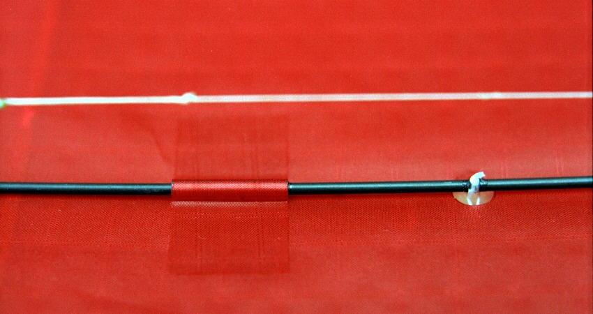
The spine is then cut to the length of the sail. I use epoxy to glue a ¼ in. piece of spine material crossways at the ends of the spine; this prevents the spine from punching through the sail. These end pieces are oriented so they are perpendicular to one of the spine’s flexure predisposition, i.e., most graphite spines show one or two preferred orientations when flexed. The bridle attachment holes are then hot cut. The points on the bow are 15% of the wingspan apart. The tail point is 2 in. from the tail. The mid-spine point is 40% of the distance from the tail point to the bow-spine crossing, and located closer to the tail. The spine is wrapped with clear ¾ in. tape in two places, under the bow and above the tail bridle point. The upper tape protects the spine from abrasion when the bow rotates as it flexes and serves as one anchor for the spine tensioner, see Photo 3 for a close-up of the nose area, see Photo 4 for a close-up of the tail. I also make a tightly fitted, but freely sliding 1 in. long tube of aluminum foil and ¾ in. clear tape on the spine between the bow and mid-spine bridle points. This tube will be taped to the sail later; its purpose is to prevent the spine from bending sideways, see Photo 5..
Then the wingtips, nose and tail of the sail are taped down (back side of the sail facing upwards) with enough tension applied to keep the sail perfectly flat. Contact cement (solvent based) is then lightly spread along the bow, and on the fold-over tabs and the sail they will contact, (I mask the sail with low-tack masking tape). After 25 minutes, the contact cement should feel just tacky. I cut the glue film at the edge of and between the foldover tabs, and then fold the tabs over the bow and down onto the back of the sail, starting at the wingtips and alternating sides. The tabs should go around the bow and straight down to the sail. A piece of 3/16 in. dowel, cut at 45 degrees, is a useful tool in laying the tabs down progressively, over the bow, then out onto the sail. No tension is used beyond what is needed to just fold the tabs over and press them down, otherwise one risks uneven tension in the sail. See Photo 6 for a close-up of the bow and leading edge intersection.
Once the tabs are done, the sail is untaped
from the work surface. The spine is then
attached using 3 in. long pieces of 1 ½ in.
wide hot cut Icarex fabric completely covered
on one side with the double sided tape. (In
effect, one makes custom “crack and peel”
tape which perfectly matches the sail). The
spine is taped at the nose first, then the
sail is tensioned again, as the tail tape
is set. If the spine has a slight curve,
the spine should be placed so that the sail
is “pot-bellied”. The spine should be in
front of the bow, and the sail should be
very flat and smooth. The bow is tied to
the spine and the nose and tail tapes are
trimmed for appearance and lowered drag.
The free- sliding tube is affixed to the
sail by 1) a short piece of double sided
tape under its length, and 2) a 1 in. by
2 in. piece of Icarex “crack and peel” wrapped
tightly around it and down onto the sail,
see Photo 5 in which the nose is to the left. I put
the tube above the mid-spine bridle point.
To minimize drag I use 12 lb. braided Dacron
fly line backing, flame-sealed to prevent
unraveling on the ends. Adjusters (tuners)
are made of small glass beads, sometimes
called Indian beads. Over the years I've
invented and borrowed the various knots and
assemblies used in the tensioner and bridle.
My goal has been to find knots and tuners
that were small (low drag), did not creep,
but were easy to loosen and adjust very precisely.
The resulting bridle is, however, rather
more complex than others commonly encountered.
But the complexity is of the sort that results
from repeating several instances of individually
simple things. The effort taken to build
this bridle is repaid many times over on
the flying field.
Figure 3 shows an exploded view of the bridle, Figure 4 is an overhand knot noose variant that loosens
easily, Figure 5 is a diagram of an adjuster (tuner). The
tuners all have three lines converging: one
line is fixed, attached by a Knot #1 noose,
the other two lines are the adjustable legs.
The adjuster holds the line's position without
slipping or jamming; it is a Larkshead variant
I call a Noose-Larkshead. To make tuning easier on the flying field,
I put a closed loop through the noose portion
of the knot to use as a “handle”. Tugging
on the fixed line and handle loop will loosen
the knot easily.
Figure 6 diagrams how the elastic is installed in
the upper bridle; Photo 7 shows how it looks when completed, the nose
of the kite is toward the left. I usually
put handle loops on only one side for field
adjustments. The bridle subcomponents are
assembled onto the kite in this order: the
roll bridle, the tail bridle, the pitch bridle,
the towline, the elastic.
Photo 5 also shows how I attach the bridle to the
frame, as seen from the rear of the sail.
Rather than a noose around the frame, I tie
a small loop in the end of the bridle, then
lash this loop to the frame and lock the
lashing in place with fast drying cement.
This permits the bridle to be removed and
reinstalled without having to cut it.
The spine is curved at low air pressures
by an elastic tensioner on the back side
of the spine. The tensioner is strung between
the outermost pieces of tape on the spine:
the tail bridle point and the bow crossing
tape. Figure 7 diagrams its construction; Photo 2 shows the completed tensioner, note that
two or more elastics can be used. The adjuster
is the noose-larkshead adjuster with one
of the adjustable legs left to dangle loose.
Photo 4 also shows the notched "riser"
made of a piece of vinyl tubing. The riser
insures that the tensioner can apply a bending
force to the spine, even when the spine is
straight, and the tubing adds a little weight
to the tail, moving the center of gravity
toward the tail, which benefits this particular
sail plan. In flight, the spine tensioner
and the bridle are so adjusted that when
the bridle elastic is fully extended, the
spine is straight.
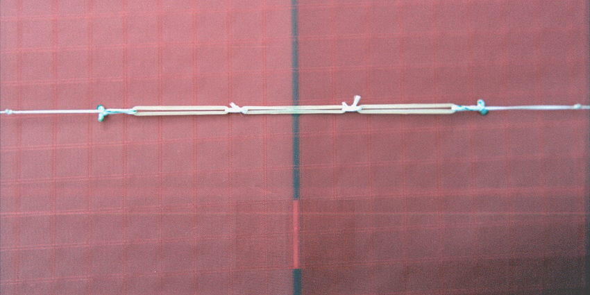
The Variable Bow Stiffness is achieved by an elastic tensioner between
the wingtips on the front side of the sail.
The tensioner is strung between the outermost
1/8 in. of the bow. I lock the outer noose
to the end of the bow with a hard setting
glue. Photo 8 shows one end of the completed tensioner,
the other end is the same. There are two
adjusters to allow the elastics to be centered.
The adjusters are the same noose-larkshead
adjuster as used in the spine tensioner above.
Photo 9 shows the centered elastics; note that two
or more elastics can be used.
With many combinations of spine and bow diameter
and all the bridle and tensioner adjustments
available, the flyer has wide latitude in
setting up and tuning the kite. I select
and tune mine as follows. I set the bridle
elastic range and the angle of attack so
that the spine is just a bit back of perpendicular
to the wind when the kite is straight downwind
and the elastic is fully extended, and yet
the kite is sufficiently yawish at the edge
of the wind when the elastic is fully contracted.
I select the kite for the wind by flying
long horizontal passes at shoulder height.
If the kite flies straight when in the center
of the wind without my giving or taking line,
then that kite is the correct one for the
wind speed. This selection results in the
ability to steer the kite during horizontal
flight by slightly giving or taking line.
Taking line increases the wind pressure and
the kite will turn toward the ground, giving
line will let the kite turn up. This control
is subtle and requires practice. Many fighter
designs show this behavior: straight flight
up to a certain pressure, then curving toward
the ground as the pressure rises further.
In the past I have always tried to eliminate
this behavior and have the kite fly straight
no matter how hard one pulled. However, this
design is fast enough so that the flyer does
not always need to achieve maximum velocity
to be competitive. Therefore, the maximum
pressure regime can be allowed to produce
a downward curving flight path, adding one
more dimension of control.
I adjust the Bow Tensioner so that all of the bow's tension is being countered
by the tensioner. This means that the slightest
wind pressure will move the wingtips inward
slightly, which makes the kite hover very
easily.
With its flexible spine and low frontal area, this kite has low enough drag to “get ahead of the line”. This shows as a significantly increased amount of curve in the flying line, affecting the kite’s attitude. This can cause the kite to behave as though it has overflown the wind: the line tension drops abruptly and the flyer loses control. To regain control the flyer must either 1) slacken the line, removing the wind pressure, to let the spine bend again to make the kite fly away from the flyer, or 2) take line in quickly, to remove the curve in the line, so that the kite is not in an overflown attitude. One can modulate the onset of this effect by changing the depth of the spine’s curvature and the tension in the spine.
Overall, the Vari-Fighter design flies more
easily than my previous designs, but it also
offers additional capabilities, requiring
the flyer to learn how to exploit them. Inexperienced
flyers have been able to fly this kite, even
when it was tuned for competition. This is
testimony to its variability making the kite
easier to fly, even though its performance
is excellent.
I am a slow kite builder. To make a Vari-Fighter takes me about 6 hours elapsed (8 hours, if I make a new design’s pattern, too), and I’m working just about every minute. But the result is worth the effort. Properly tuned, these kites are an absolute delight to fly. I hope others can share the delight.