Final Sail and
Bridle Plan for the BDub Project
(In which
the completed kite comes of age after almost a year of prototypes and
tweaking)
Well, here at last is the plan so many have
been waiting for. I originally wanted a kite that was easy for all levels of
flier to play with, easy to fly, precise, trickable, light wind and
NO oversteer. After many trials and tribulations - not to mention
a learning curve as steep as the north face of the Eiger - I feel confident that
the kite fills all these requirements. You don't have to trick with it, but you
can do. You don't have to just fly figures, but you can do that too. It will
allow a complete novice to realise how easy dual line kites are to fly but will
also let them do more advanced things as they progress up the path of
learning.
Enough of the waffle, then. On to the plans. I have
tried to make this more in the way of a guide. There are no 'proper' ways to sew
the seams, you can overlap and french seam if you want, but I personally just
sew layer to layer. That may be OK for this kite as it is meant to be a low wind
(read low stress) design. Other designs may need stronger seams. What I intend
to present here is the way I made the kite and let you go from
there. If you need more in depth advice, you can always email me.
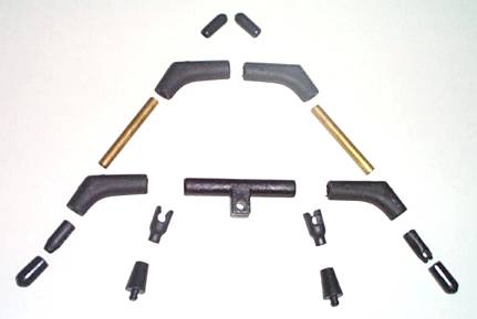 To start with, you are going to
need some fittings. Whatever particular manufacturer you choose is up to you,
but here's what you must have: As you can see, it's fairly routine stuff. In
there, you have a 4mm centre spreader, 2 x 4mm standoff grabbers (for 2 mm
whiskers) and corresponding 2 x sail grabbers, 2 x 5 mm end caps, 2 x 4 mm arrow
nocks, 4 x 4mm spreader to leading edge connectors, 2 x 4 mm brass ferrules, and
2 x 4 mm end caps. Make sure you have brass ferrules rather than the lighter
aluminium ones as the extra weight is necessary, I'm afraid. You could use
lighter ones but this would restrict the trickiness somewhat as the frame is
only 4 mm RCF. In the final model, the one stepped through in this plan, I
actually used 4 mm solid carbon, so the brass ferrules were not strictly
necessary. In the first model though, they made rather a big difference to the
flight characteristics. So, to sum up, if you frame your kite in solid carbon,
you can use any ferrules you want. If hollow carbon, then use the brass ones.
The positioning of the ferrules is important too, depending on your choice of
framing materials - but more on this later.
To start with, you are going to
need some fittings. Whatever particular manufacturer you choose is up to you,
but here's what you must have: As you can see, it's fairly routine stuff. In
there, you have a 4mm centre spreader, 2 x 4mm standoff grabbers (for 2 mm
whiskers) and corresponding 2 x sail grabbers, 2 x 5 mm end caps, 2 x 4 mm arrow
nocks, 4 x 4mm spreader to leading edge connectors, 2 x 4 mm brass ferrules, and
2 x 4 mm end caps. Make sure you have brass ferrules rather than the lighter
aluminium ones as the extra weight is necessary, I'm afraid. You could use
lighter ones but this would restrict the trickiness somewhat as the frame is
only 4 mm RCF. In the final model, the one stepped through in this plan, I
actually used 4 mm solid carbon, so the brass ferrules were not strictly
necessary. In the first model though, they made rather a big difference to the
flight characteristics. So, to sum up, if you frame your kite in solid carbon,
you can use any ferrules you want. If hollow carbon, then use the brass ones.
The positioning of the ferrules is important too, depending on your choice of
framing materials - but more on this later.
 I have, luckily, come across a
supplier of good first quality K42 ripstop at a reasonable price and in several
colours. (email me for the supplier) This is unusual for the UK and had some
bearing on the pattern for this kite. The prototypes were made from ripstop of
varying qualities/weights and this meant that, had I made them up as simple two
piece sails as I did for this model, then the balance would have suffered for
such a light kite. There are no real reasons, other than looking good, to make
this a multi-panelled kite because there will, hopefully, not be enough pressure
on the sail to cause stress to become an issue. Apart from that, it's early
summer and I should be out flying rather than in here typing and sewing. The
only reason I am in here now and not doing this two months ago is that
the damned bridle took so long to get right. To the point. Get your decent
ripstop and lay it out for a few hours - the longer the better. I do this
because no matter where I seem to get the stuff from, it comes pre-creased in
all the wrong places and the stuff has a chance to relax. I prefer not to
warm-iron it, and letting it sit out flat for a time is nearly as good. Note in
the pic the strategically placed pack of Elastoplast on the window sill.
Obviously, I'm ready to cut the stuff soon so am getting prepared...
I have, luckily, come across a
supplier of good first quality K42 ripstop at a reasonable price and in several
colours. (email me for the supplier) This is unusual for the UK and had some
bearing on the pattern for this kite. The prototypes were made from ripstop of
varying qualities/weights and this meant that, had I made them up as simple two
piece sails as I did for this model, then the balance would have suffered for
such a light kite. There are no real reasons, other than looking good, to make
this a multi-panelled kite because there will, hopefully, not be enough pressure
on the sail to cause stress to become an issue. Apart from that, it's early
summer and I should be out flying rather than in here typing and sewing. The
only reason I am in here now and not doing this two months ago is that
the damned bridle took so long to get right. To the point. Get your decent
ripstop and lay it out for a few hours - the longer the better. I do this
because no matter where I seem to get the stuff from, it comes pre-creased in
all the wrong places and the stuff has a chance to relax. I prefer not to
warm-iron it, and letting it sit out flat for a time is nearly as good. Note in
the pic the strategically placed pack of Elastoplast on the window sill.
Obviously, I'm ready to cut the stuff soon so am getting prepared...
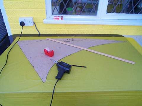
 While the ripstop is settling out,
you can draw out the sail pattern and decide if you want lots of panels or not
many. Remember that too many panels will add unacceptable weight to what is
really a light wind kite. If you want lots of colours/panels then I suggest you
do what I intend to do next - scale it up by about 140% and use 6 mm RCF or
Skyshark rods. Then you can do circles and infinity loops to your hearts content
in 16 mph winds. Whatever - back to the plan, I draw mine out on brown paper
first to give me a cut-uppable template to help with cutting out the ripstop
later. It may not look pretty but it has all the info on and is relatively
cheap. It also has two sides for when you cock up.
While the ripstop is settling out,
you can draw out the sail pattern and decide if you want lots of panels or not
many. Remember that too many panels will add unacceptable weight to what is
really a light wind kite. If you want lots of colours/panels then I suggest you
do what I intend to do next - scale it up by about 140% and use 6 mm RCF or
Skyshark rods. Then you can do circles and infinity loops to your hearts content
in 16 mph winds. Whatever - back to the plan, I draw mine out on brown paper
first to give me a cut-uppable template to help with cutting out the ripstop
later. It may not look pretty but it has all the info on and is relatively
cheap. It also has two sides for when you cock up.
Here's the nitty-gritty
details of the sail, with layout measurements and all that. No, you can't have
it in .pdf format 'cos I'm imminently going to be made redundant and all the
tame draughtsmen have already gone. You'll just have to make do with a sad old
.gif pic and get to work with a rule and a big pen. The same as I had to this
time. It's only fair, don't you think?

There now follows the
obligatory list of measurements. It's a big list but not too hard to put down on
paper. I had intended to do this on graph paper but when I started, it just made
the whole thing look too complicated. Here goes:
| A - B |
730 mm |
| A - C |
140 mm |
| A - D |
370 mm |
| A - R |
500 mm |
| A - E |
530 mm |
| A - F |
655 mm |
| A - I |
1200 mm |
| A - L |
600 mm |
| L - K |
60 mm |
| O - P |
50 mm |
| M - N |
55 mm |
| B - J |
380 mm |
| J - I |
700 mm |
| B - N |
190 mm |
| J - P |
350 mm |
| E - J |
320
mm |
I have received a CorelDraw
template from Kenton (download it here) which you
should be able to take down to your friendly printer and have a full size copy
run off fairly cheap - thanks the KW for this.
Morino Enrique has also done an Autocad
rendering of the plan, (download it here). Here's
what he has to say about it:
"This is the sail pattern in AutoCad R14
format, the drawing is in millimeters and 1:1 scale, the size of the sheet
is ANSI "E" (normalized) therefore you can plot it without problem in a standard
plotter."
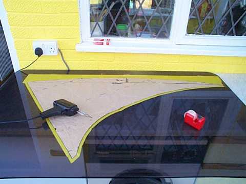
And so we come to the cutting section of
the plan. Once you have transferred the above plan to paper/plastic/whatever to
use as a template, you're ready to hack up some ripstop. (I have the grain of
the ripstop running in the direction of 'A' to 'I' in the plan above.) The plan
makes NO allowance for seams, so you'll have to add your own. As I intend
to have a Dacron leading edge, there will be no seam allowance there, but there
will be a seam along the trailing edge and there is also an allowance to
be made for joining the two bits of the sail together. I add about 10 mm to the
trailing edge and centre line as this is all I think I need for the leach line
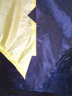
and to join the two halves. In this picture, you can just make out the pencil
line I added for this allowance. As you can see, I use a soldering gun with the
tip filed down to give a knife edge. Also, I use an old glass table top as a
cutting board and the ripstop is taped to this. Then I grab a bundle of offcut
nylon and rub it all over the surface - to help the ripstop lay flat. The
template is then taped down onto the ripstop and I'm ready to cut. No doubt you
can see that the cutting is done freehand and it's a buggar of a job to get a
decent line. All I can say is that practise will help, and the slower you move
the gun, the more wobbles you'll develop along your line. The straight edges can
be done using a straight edge - but there's only one on this pattern.
Shame.

A couple more pics of the cutting here. The
first shows the sail nearly cut. At this point I turn the glass around 180
degrees so that I'm closer to the other side. Easier to cut. The second shows
the two halves of the sail ready to be sewn up.
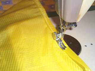
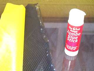 As a personal thing here, when
sewing up kites, I tend towards the simple approach to things. For this reason,
I have a nasty habit of using a light water-based glue stick to hold the pieces
together while I sew them. Something along the lines of a Pritt-Stick is ideal
and any excess sticky stuff can be rubbed off with a finger. In the picture
here, you can see the two halves of the sail ready to be glued together and
sewn. When they are attached to each other, I like to draw a line with a
straight edge (if I'm sewing a straight edge, of course) and a pencil to give me
something to follow with the sewing machine. That way I get a reasonably
straight seam and the sail has no awkward little humps and bumps in it where it
crosses the spine. Now the plan gets a bit picture intensive. Brace yourself,
it's easier to show what I've done rather than to try to waffle on about how to
do something...
As a personal thing here, when
sewing up kites, I tend towards the simple approach to things. For this reason,
I have a nasty habit of using a light water-based glue stick to hold the pieces
together while I sew them. Something along the lines of a Pritt-Stick is ideal
and any excess sticky stuff can be rubbed off with a finger. In the picture
here, you can see the two halves of the sail ready to be glued together and
sewn. When they are attached to each other, I like to draw a line with a
straight edge (if I'm sewing a straight edge, of course) and a pencil to give me
something to follow with the sewing machine. That way I get a reasonably
straight seam and the sail has no awkward little humps and bumps in it where it
crosses the spine. Now the plan gets a bit picture intensive. Brace yourself,
it's easier to show what I've done rather than to try to waffle on about how to
do something...
The first thing to do,
then, is to sew the two halves of the sail together (assuming you have
done as I have and made each half from a single piece of ripstop). This is
a good time to double check that both halves are the same shape!
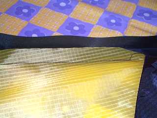
 Next, it's a case of folding and sewing the trailing
edge seams. Take it slowly - again, a little at a time - remembering that you
need to make the seam deep enough to be able to feed in a leach line later on,
as well as the piece of wire that makes it easier to get this line through the
seam.
Next, it's a case of folding and sewing the trailing
edge seams. Take it slowly - again, a little at a time - remembering that you
need to make the seam deep enough to be able to feed in a leach line later on,
as well as the piece of wire that makes it easier to get this line through the
seam. 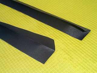 Once that's done, I cut the two lengths of
Dacron that will form the leading edges and sew them in place. The edge of the
sail needs to be in right up to the crease of the Dacron. There's alot of advice
around about sewing Dacron onto a curved edge, so to muddy the waters further,
here's how I do it.
Once that's done, I cut the two lengths of
Dacron that will form the leading edges and sew them in place. The edge of the
sail needs to be in right up to the crease of the Dacron. There's alot of advice
around about sewing Dacron onto a curved edge, so to muddy the waters further,
here's how I do it.
-
-
- Cut the Dacron to the length of
your leading edge.
- Fold the Dacron in half along it's
length and crease tightly, perhaps by drawing the crease over a sharpish
corner such as a table edge.
- Sew the sail into one side of the
Dacron, a little at a time and following the curve of the sail.
- Fold the Dacron over the sail and
sew again - this line of stitching will close the leading edge and make
the pocket for the spar.
 >>>
>>>
Simple really !
Next, use another piec of Dacron for the
nosepiece. This is how I do it, your method may vary.
And two more for the base of the
spine and the centre spreader connector.
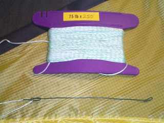
Now you can thread the leach line through
the trailing edge. I use an artfully bent piece of garden wire and some 75 lb
polyester line.

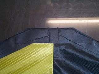
Believe it or not, another two pieces of
Dacron, this time for the stand off sail grabbers...
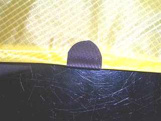
... attached as shown...
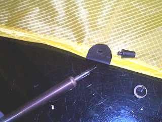
and holed with a soldering iron ready for
the connector...
the back of which I heat with a lighter
and press the blob of plastic down to stop it falling out and also to lower it's
profile to lessen the chances of line snags.
Then, cut out the gaps in the leading edge
Dacron for the spreader connectors...
... and press a hole in each wing tip as
shown. (Notice the large amount of spare leach line. Less chance of it getting
pulled back up the seam by mistake)
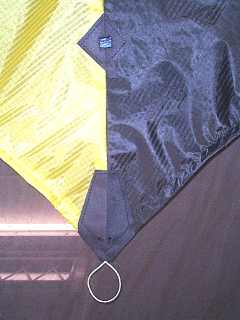
Then, two small holes in the Dacron at the base of the spine - hard to
see here, but they are for the loopof line that will keep the sail taut - and a
square hole for the centre spreader connector.
Once you get this far, then it's just a
case of getting the carbon onto the sail and sorting the bridle! So let's get on
with the frame and the rest. In this kite, I used 4 mm solid carbon fibre, which
came in 1.5 m lengths. I only got three lengths as I had some 4 mm hollow left
from an earlier prototype. This gave me a cutting list as follows:
2 x ( 90 cm and 60 cm)
1 x 70 cm and 2 x 34 cm (12 cm waste here)
To give me 2 x 60 cm bottom spreaders, 2 x
124 cm leading edges (using the ferrules at the wing tip end) and 1 x 70 cm
spine. For the top spreader, as I said, I used hollow 4 mm, length was 56 cm.
Each assembled leading edge has an end cap at the pointy end and an arrow nock
at the other, with a ferrule in the middle somewhere. The rest of the frame is
fairly self-explanatory. Don't forget that the reason for the ferrule at the
bottom end is to help the kite in rotations and fades. It also makes for cheaper
repairs as you will find that when tip-stabbing, the bottom of the LE will fail
first.
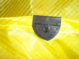
Some notes on the stringy bits
other than the bridle:
I refuse to use bungees when I
make a kite, preferring to use loops of line. Seems like cheating to me if the
saill is a bit uneven. On this detail, you can see how I attach the loop through
the sail and around the nock. What you can't see is that the loop goes around
the spine behind the sail. Also, peeping through is the leach line, which also
goes over the nock, and the trick line.
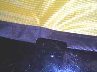
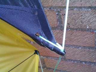
Here is a view of the wingtip
assembly. The tip tensioning loop and the leach line both hook over the nock,
and the trick line is tied around the spar itelf and comes out from a small hole
poked in the end of an end cap. This looks neat and also stops the two loops
coming off the nock in flight/groundwork.

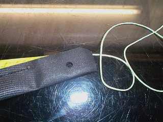
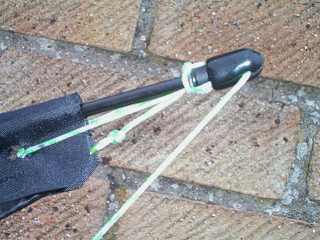
Here you can see how the 'W'
of the trick line is formed by making two large loops and tucking them under the
stand off sail grabbers. Remember that the trick line should hardly, if at all,
alter the geometry of the kite. So keep it taut but not tight.
Next, the infamous reverse turbo bridle,
for which I also use 75 lb poyester line. I fine this much more responsive on a
light wind kite than the proprietary bridle line as it is much more pliable and
no flier input is wasted bending stiff bridles. The reason for a reverse turbo
bridle came from an attempt to originally configure an active bridle for the
kite but which gave me severe problems, not the least of which was that at
the start, the sail configuration didn't suit the active system. What it
did suit, however, was an active bridle minus the activator leg. Hence, a
reverse turbo bridle was the way to go, offering responsiveness whilst at the
same time keeping the flier in complete control.
The bridle itself is made up
of just five bits of string. Simple really, but it was a buggar to get
right.
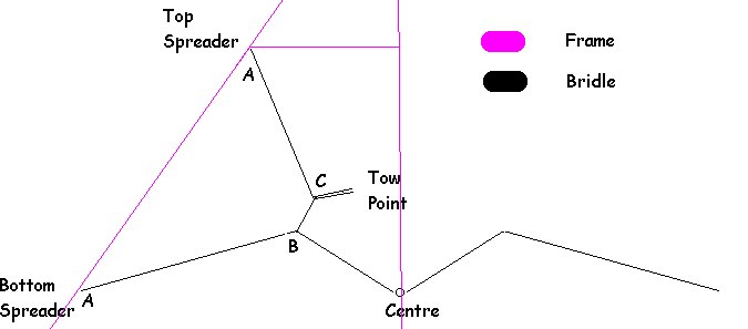
The line from A to B to Centre is one piece
and continues over to the other leading edge. 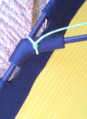 This part of the bridle is 1800mm including an
allowance for tying to the leading edge. To make this part of the bridle, cut
your line to length and fold it in half. Tie the centre of the line around the
spine, just below the lower spreader connector, giving you two lines coming from
the spine. Tie one to the left lower spreader/LE connector, and the other to the
right lower spreader/LE connector (Lower 'A' in the drawing, illustrated in the
picture - make sure you go round the spar and pull tight). The line from the
upper 'A' to 'C' to 'B' is one piece, 470mm long - again, including an allowance
to tie the line to the LE at the upper spreader connector. It is tied to the
point 'B' using a sheet bend knot. From the 'C' to the tow point is a loop of
line tied from a piece about 175mm long and larks-headed (double if you can) to
the lower bridle. Point 'B' is 390mm from the knot at lower point 'A' and point
'C' is 350mm from the knot at upper point 'A'. Adjustment, if needed is by
moving point 'B' closer or further from the spine and point 'C' higher or lower,
depending on wind strength. These sizes have been reached after many tortuous
hours out in the field so I can guarantee you can fly with them. However, your
style may be different to mine, so mark these points as standard and have a play
yourself.
This part of the bridle is 1800mm including an
allowance for tying to the leading edge. To make this part of the bridle, cut
your line to length and fold it in half. Tie the centre of the line around the
spine, just below the lower spreader connector, giving you two lines coming from
the spine. Tie one to the left lower spreader/LE connector, and the other to the
right lower spreader/LE connector (Lower 'A' in the drawing, illustrated in the
picture - make sure you go round the spar and pull tight). The line from the
upper 'A' to 'C' to 'B' is one piece, 470mm long - again, including an allowance
to tie the line to the LE at the upper spreader connector. It is tied to the
point 'B' using a sheet bend knot. From the 'C' to the tow point is a loop of
line tied from a piece about 175mm long and larks-headed (double if you can) to
the lower bridle. Point 'B' is 390mm from the knot at lower point 'A' and point
'C' is 350mm from the knot at upper point 'A'. Adjustment, if needed is by
moving point 'B' closer or further from the spine and point 'C' higher or lower,
depending on wind strength. These sizes have been reached after many tortuous
hours out in the field so I can guarantee you can fly with them. However, your
style may be different to mine, so mark these points as standard and have a play
yourself.
Well then, all you have to do
now is tie on some longer bits of string and go fly!
Enjoy.
A couple of pics to look
over...
 .
.
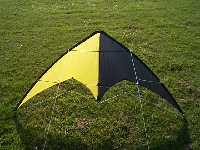
The completed Mark III BDub. I
guess it's no longer a BDub really, BDub is short for BW, as in black and white.
Never mind. Think of a better name and email me...

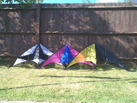
Happy families. Alas, Mk II
fell by the wayside a while ago. It had a solid fibreglass frame and flew in
extremely high winds. It just couldn't nosedive too well in those same
winds.
If you make one of these, send
me a pic to add here.
Aik
are@tesco.net
StopPress!!! MK
II Makes A Comeback!!!
After a bit of
sewing and repair, Mk II makes a stunning return to the family. Still a bit
harder to fly with those solid glass fibre leading edges and upper spreader, but
the rest is now 6mm RCF. Not so twisty in higher winds.
Kenton Williams has made his
first BDub - click here to see it and his comments on the construction (UPDATE - he's made
another one! Both pics and stuff on this link)
So has Alexander in New
Zealand - click here to see theirs.
... and Terry Walker has
finished his, click here to see it.
... and M. Hess has made his
at last, click here for his.
Then come back here and
click here for a picture of the latest BDub derivative - a 130% scale up with
straighter LEs and a 6 mm Exel frame with 3 mm stand offs - destined to become a
precision/ballet kite. How the mighty have fallen! (This one even has a fully
activated bridle.)
Or go here for a look at the
BDub's very own FAQ page.
© Arthur Edwards, 2001 - You may decide to make this kite
and see if it really is as good as it looks. If you do, then please don't sell
it to anyone. I never sold the plans to you, so it's only fair - isn't it?